Updated: May 28th 2015
 This circuit is modeled very, very, loosely after the tone of Robben Ford and his Dumble. It's not another "clone" pedal and doesn't make any claim to be one. Special thanks to Burchtone for the original schematic and Katopan for the PCB layout.
Current Status:
We just had a second batch of PCBs (another 200) made up and they are now available for sale.
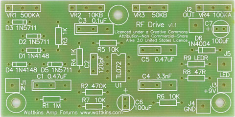
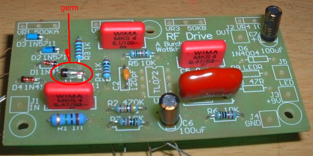
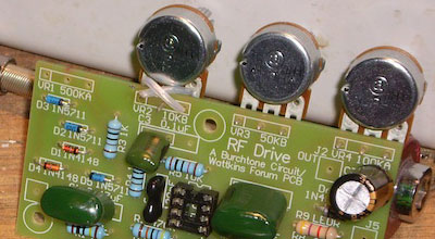
Top of RF Drive PCB:
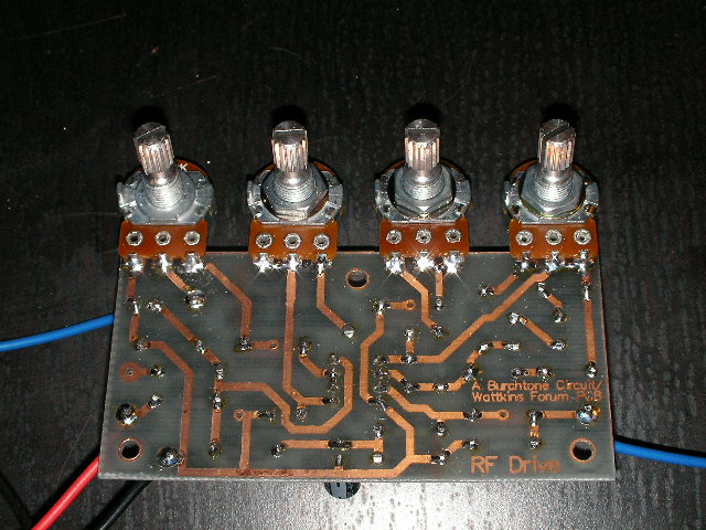
Bottom of RF Drive PCB:
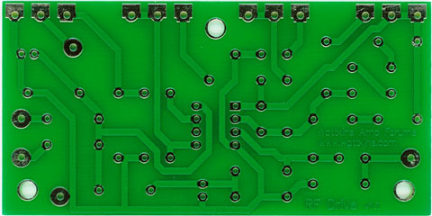
Please note these pictures are not to scale. The actual PCB is slightly smaller.
 Obtaining the PCB:
You can buy the official RF Drive PCB here:
http://www.tubeface.com/wattkins/rf-drive
Schematic:
http://www.wattkins.com/files/wattkins/RFD%20Schematic%20CM1.pdf
Component Choices:
Parts thread here: http://www.wattkins.com/node/16866 (incomplete)
- Resistors - 1/4 to 1/2 watt, metal or carbon film (your choice).
- Caps - You don't need High Voltage rated caps as this is only a 9V pedal circuit. But feel free to experiment with different types. You'll notice there are 0.2" and 0.4" spaced pads for the 4 signal caps which allow for different physical sizes. A lot of folks have tried Sozo's, and like their sound, but they are a bit on the humungous size for this project. Also recommended are the Russian green paper-in-oil caps but, again, these are on the big size as well. A lot of people are happy with the smaller and more inexpensive (but high quality) Panasonic "greenie" caps too.
- Electrolytics - Once again it's only a 9V circuit. 16V or above will be fine. Just be sure to get a size that has 0.1" lead spacing so it goes into the PCB easy.
- Pots - 16mm pots with 1/4" shaft if you want to PCB mount them, or any type if you wire to them off-board.
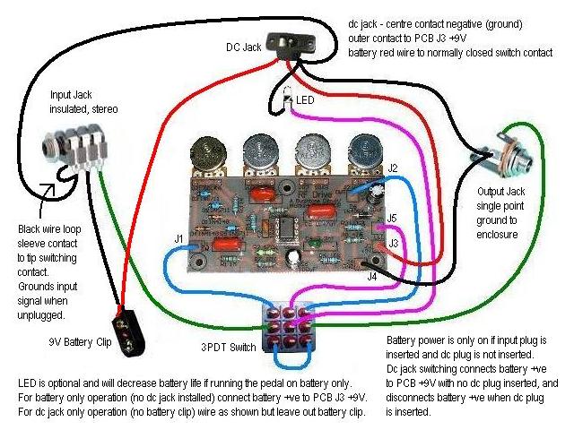
- Switch - Normal stomp box style footswitch. 3PDT if you want to switch an LED as well as true bypass, DPDT if you don't want an LED. There's a wiring diagram in the thread.
- Enclosure - Totally up to you, depends what you can get and what look you want. Diecast aluminium box, instrument enclosure, diy folded sheet aluminium, purlin, etc.
- Jacks - Use whatever you like as long as the input jack is stereo. That way the ring is used to connect the battery when you plug an instrument cord in. One recommendation is to use an insulated jack (i.e. Cliff) for the input and a non-insulating one (i.e. Switchcraft) for the output jack, which becomes the single earth reference connection to the enclosure and the star ground point. But both jacks can be the same.
- LED - Your choice.... Pink with purple polkadots if you can find one.
Layout:
Threads:
RF Drive for DUMMIES:
http://www.wattkins.com/node/16005
Other threads:
http://www.wattkins.com/node/16635
http://www.wattkins.com/node/16645
Obtaining the PCB:
You can buy the official RF Drive PCB here:
http://www.tubeface.com/pcb/rf-drive-pcb
Parts List:
The official parts list is here (add enclosure of choice and knobs):
http://www.wattkins.com/files/wattkins/RFD%20PCB%20Parts%20List.txt
http://www.wattkins.com/files/wattkins/RFD%20PCB%20Parts%20List.xls
Drill Plans & Labels:
Pot spacing on the PCB is 0.9” giving 2.7” or 68.58mm between the first and last pot spindle center. The hole size normally specified for 16mm pots is 7.5mm but an 8.0mm or 5/16” drill will allow adequate clearance and still support the mounting washer and nut. These files are sized for 600 dpi printing. If you print with no scaling they will be spaced to match the PCB. This should be checked before drilling or adhering graphic against the measurements above.
http://www.wattkins.com/files/wattkins/RFD_PCB_Pot_Drill_Crosshairs.pdf (small crosshairs spaced 0.9” apart)
http://www.wattkins.com/files/wattkins/RFD_PCB_Pot_Drill_Circles.pdf (5/16” circles with centre crosshairs)
http://www.wattkins.com/files/wattkins/RFD_PCB_Pot_Dials.pdf (dial graphic to suit up to a standard 18mm knob)
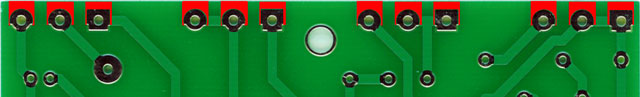
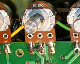
Pot Orientation:
This picture is of a prototype PCB, not the finished PCB.
Errata:
The KY mod replaces D5 with a germanium diode such as 1N34A which provides a "creamy, smoky type of distortion" (thanks to kyoungsteadt for this):
The following information only applies to the first batch of 100 PCBs. This DOES NOT apply to the v1.1 PCB as these items are now fixed:
- PCB Pot Pads
There are fill areas on the PCB that extend the pot pads (that can be used to solder a non-PCB pot leg to the PCB). Unfortunately, the solder mask is covering these fill areas. In order to expose these fill areas, you will need to very carefully scrape away the solder mask until the copper pad underneath is exposed. This area is identified in red in the picture below:
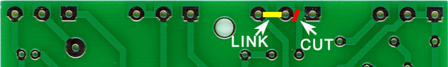
- 10k Linear Bass/Attitude Control
The 1.0 PCB was correct according to the schematic, but we found that the Bass/Attitude control worked in a counter-intuitive manner. The signal became smoother and less distorted as the pot was turned clockwise. Those using wires between the pot and the PCB can simply reverse the outside two wires. Those using PCB-mounted pots will need to make a minor modification to the PCB by cutting the trace linking the pot wiper (center) and soldering a jumper from the wiper to the other side of the pot:
Here's an example of the mod from GT350:
Another way of doing this, without cutting the PCB, is to solder the pot lead as follows (thanks to cGil for the Origami lesson):

wattkins.com RF Drive PCB by Wattkins Amp Forums is licensed under a Creative Commons Attribution-Noncommercial-Share Alike 3.0 United States License.
Based on a work at www.wattkins.com.